

Steel Tonnage Estimator — ReadMe
About this guide
The Steel Tonnage Estimator gives a budget weight of steel for a pre-engineered (PEB) building, broken down into primary, secondary, crane and accessory steel. This guide explains every input on the form, in the order the form shows them.
- Each table lists the input as it appears on screen, its unit, the default value, what it means and a sensible range.
- Inputs that appear only after a tick or a choice say so in the last column (for example, crane inputs appear once EOT cranes is ticked).
- Diagrams show where each dimension is measured on the building.
- Several buildings can be added as tabs with Add building; each tab has its own full set of inputs, and the project total adds them up.
The result is a budget estimate for comparing options and checking quotations, typically within ±10–15% of a supplier's detailed design. It is not a substitute for the stamped design and drawings from the PEB supplier or structural consultant.
Quick start
- Enter width, length and eave height under Building.
- Pick the site city under Wind; it fills the wind speed and seismic zone.
- Tick EOT cranes, Mezzanine or Canopies if the building has them.
- Read the total and the breakdown on the right. Change one input at a time to see what drives the weight.
1. Building
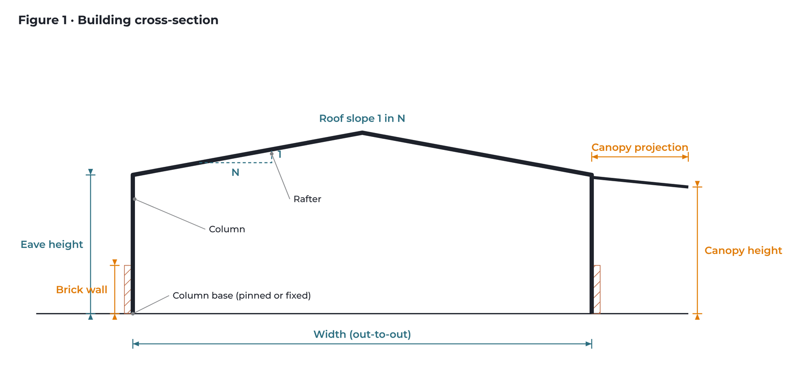
These inputs fix the size and shape of the building. Width and eave height have the biggest effect on tonnage, because frame weight grows faster than span.
| Input | Unit | Default | What it means | Guidance |
|---|---|---|---|---|
| Building name | – | Building A | A short label used on the tab and in the project total. | Workshop A, Shed 2, Stores |
| Width (out-to-out) | m | 30 | Overall width across the building, measured to the outer face of the steel line, as PEB suppliers quote it. Sets the frame span. | 8–200 m. Most clear-span sheds are 20–45 m. |
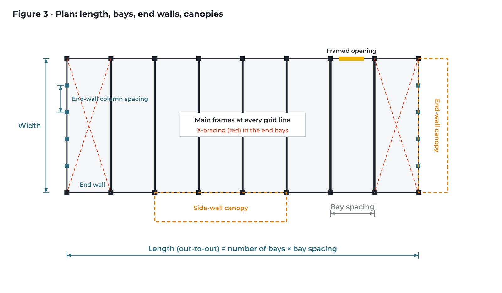
| Length (out-to-out) | m | 60 | Overall length along the ridge, outer face to outer face. Sets the number of frames and the run of purlins, girts and crane runway. | 6–400 m |
| Eave height | m | 8 | Height from finished floor to the eave, where the roof rafter meets the column. Taller columns catch more wind and sway more. | 3.5–20 m. With cranes, at least rail level + about 2 m. |
| Roof slope, 1 in | – | 10 | The roof rises 1 m for every N m measured across. 1 in 10 is about 5.7°. Flatter roofs need deeper rafters. | 1 in 10 is standard for PEB; 1 in 20 for very wide roofs. |
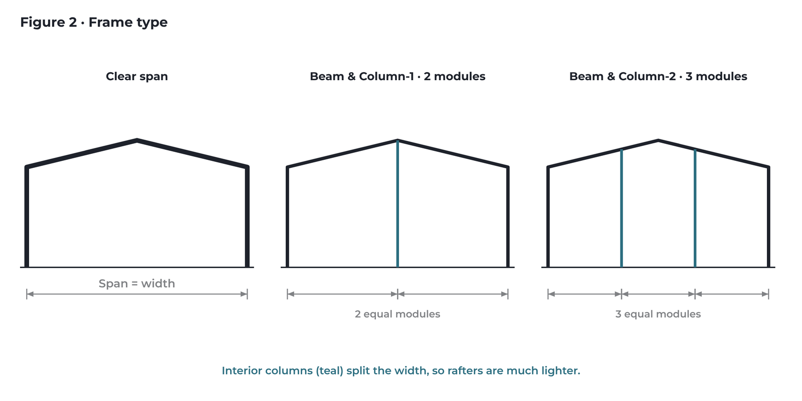
| Frame type | – | Clear span | Clear span: no columns inside the building. Beam & Column-1, -2 …: one, two or more lines of interior columns that split the width into equal modules, giving much lighter rafters. | Choose Beam & Column when the layout can take interior columns. |
| Number of bays | no. | 0 | Number of bays along the length, as a quotation writes it (for example 8 @ 7.5 m). | Enter 0 to let the tool choose equal bays near the target spacing. |
| Target bay spacing | m | 7.5 | Preferred distance between frames. The tool rounds to equal bays over the length. | 6–8 m is usually the most economical. Shown only when Number of bays = 0. |
| End frames | – | Non-expandable | Non-expandable (bearing frame): light end-wall columns with a simple rafter, cheapest. Expandable (rigid frame): a full portal frame at each end so the building can be extended later. | Pick Expandable if a future extension is planned. |
| Column bases | – | Pinned | Pinned: the column can rotate at the base; smaller foundations. Fixed: the base resists moment; stiffer and often lighter frames, but bigger footings and anchor bolts. | Pinned is the PEB norm. Fixed suits tall or crane buildings. |
2. Design code
Choose the rules the steel is sized to. Indian Standards is what government, PSU and most consultants specify; MBMA practice matches how many PEB suppliers design, and usually gives 10–15% lighter frames. Wind and seismic loads always come from Indian codes, because the site is in India.
| Input | Default | What it means | Guidance |
|---|---|---|---|
| Design basis | Indian Standards | Sets the three choices below in one go. Indian Standards: IS 800, IS 801, IS 875. MBMA practice: AISC 360, AISI S100, ASCE 7 combinations. Custom mix: pick each one yourself. | Use MBMA to compare like for like with a supplier quotation designed to MBMA. |
| Frames and members | IS 800:2007 | Code used to size frames, end walls, crane girders and mezzanine members. IS 800:2007 (limit state) or AISC 360-16 (LRFD). | AISC allows more for slender, tapered PEB webs. |
| Purlins and girts | IS 801 / IS 800 | Code used to check cold-formed Z purlins and girts. IS 801 (Indian) or AISI S100 (North American). | Both give similar sections at typical spans. |
| Load combinations and deflection limits | IS 800 Tables 4 and 6 | IS: load factor 1.5 on dead, live and wind, with IS 800 Table 6 deflection limits. MBMA: ASCE 7 LRFD (1.2 dead, 1.6 live or wind), drift checked under a 10-year wind, limits from AISC Design Guide 3. | Seismic forces keep the IS factor of 1.5 under both. |
3. Cladding and roof loads
These are the gravity loads the roof and walls carry, in kilonewtons per square metre (1 kN/m² ≈ 100 kg/m²).
| Input | Unit | Default | What it means | Guidance |
|---|---|---|---|---|
| Roof sheeting + insulation | kN/m² | 0.10 | Weight of roof sheet, insulation and fixings. | 0.47 mm sheet + 50 mm insulation ≈ 0.08–0.10. Sandwich panels 0.12–0.15. |
| Wall cladding | kN/m² | 0.08 | Weight of wall sheeting and fixings carried by the girts and columns. | 0.05–0.10 |
| Collateral (services, lights) | kN/m² | 0.15 | Allowance for services hung from the roof: lights, cable trays, sprinkler pipes, ducts. | 0.10–0.15 typical; 0.25+ for heavy HVAC or process piping. |
| Brick wall height below sheeting | m | 3 | Height of the masonry (dado) wall at the base of the walls. Girts and sheeting start above it. | Enter 0 for full-height sheeting. |
| Rooftop solar panels | tick | Off | Adds the weight of solar panels and mounting rails to the roof. | Tick if solar is planned now or later. |
| Solar load | kN/m² | 0.15 | Weight of PV modules and rails. Shown only when solar is ticked. | About 0.15 for rooftop PV on aluminium rails. |
| Roof live load | – | IS 875 Part 2 | Load from maintenance people and equipment on the roof. IS 875 Part 2: 0.75 kN/m² for slopes up to 10°, reducing above that. 0.57 MBMA reduced: as many suppliers use. Enter value: your own figure. | Use the value in the client's design basis if there is one. |
| Roof live load (value) | kN/m² | 0.75 | The figure used when Enter value is chosen. | 0.4–1.5 |
4. Wind
Wind usually governs the frames and purlins of a light steel shed, so these inputs matter. Pick the site first: it fills in the wind speed and seismic zone, which you should then confirm for the exact plot.
| Input | Unit | Default | What it means | Guidance |
|---|---|---|---|---|
| Site (sets wind and zone) | – | Mumbai | Fills the basic wind speed (IS 875 Part 3, Annex A) and seismic zone (IS 1893) for about 40 Indian cities. Choose Custom to type your own. | Nearby districts can differ: check the code maps for the exact site. |
| Wind method | – | IS 875 Part 3 | IS 875 Part 3: the Indian Standard, as consultants and PSUs specify. MBMA / ASCE 7-10: how many PEB suppliers design, using the speed in their quotation. | Use ASCE to check a supplier's quotation like for like. |
| Basic wind speed Vb | m/s | 44 | 3-second gust speed at 10 m height in open country, 50-year return period, from the IS 875 wind map. IS method only. | 33 (Bengaluru) to 50 (east coast) to 55 (north-east). |
| Terrain category | – | 2 | How rough the ground around the site is. 1 open sea or flat land, 2 open land with scattered buildings, 3 built-up industrial or suburban area, 4 dense city. Rougher ground lowers the wind. IS method only. | 2 suits most industrial plots. |
| Risk coefficient k1 | – | 1.00 | Return-period factor. IS method only. | 1.08 for buildings that must stay usable after a storm (hospitals, emergency facilities). |
| Topography k3 | – | 1.00 | Increase for sites on hills, ridges or cliff edges. IS method only. | 1.00 for flat ground. |
| Cyclone factor k4 | – | 1.00 | IS 875 Part 3 requires 1.15 for industrial buildings within 60 km of the coast in cyclone-prone regions. IS method only. | Most of the east coast and the Gujarat coast need 1.15. |
| Wall openings (internal pressure) | – | 5–20% | How much of the wall area is open (doors, shutters, louvres). Wind entering the building pushes up on the roof from inside. Under 5%: Cpi ±0.2. 5–20%: ±0.5. Over 20%: ±0.7. IS method only. | Warehouses with dock doors are usually 5–20%. |
| Design wind speed | km/h | 158 | Wind speed as written in the supplier's quotation (for example 180 km/h), treated as an ASCE 7-10 ultimate speed. ASCE method only. | Copy it from the quotation. |
| Exposure category | – | C | ASCE 7 ground roughness. B urban or suburban, C open terrain, D flat open ground facing the sea. ASCE method only. | C for most industrial plots, D on the coast. |
| Enclosure | – | Enclosed | Enclosed: small openings. Partially enclosed: a large opening on one wall, which raises internal pressure and uplift. ASCE method only. | Choose partially enclosed for open-fronted sheds. |
5. Seismic
Earthquake forces rarely govern light steel sheds, but they can in zones IV and V or with a heavy roof such as solar plus insulation.
| Input | Unit | Default | What it means | Guidance |
|---|---|---|---|---|
| Include seismic loads | tick | On | Applies IS 1893 earthquake forces at the eaves. | Leave on. |
| Seismic zone | – | III | From the IS 1893 Part 1 zone map. Zone factor Z: II = 0.10, III = 0.16, IV = 0.24, V = 0.36. | Set automatically by the site city. |
| Importance factor | – | 1.0 | 1.0 general buildings, 1.2 buildings with many occupants (schools, offices), 1.5 hospitals and critical facilities. | 1.0 for most factories and warehouses. |
| Response reduction R | – | 3 | How much the frame can absorb by yielding. 3 for ordinary moment-resisting steel frames. | Use up to 5 only with special ductile detailing. |
6. EOT cranes
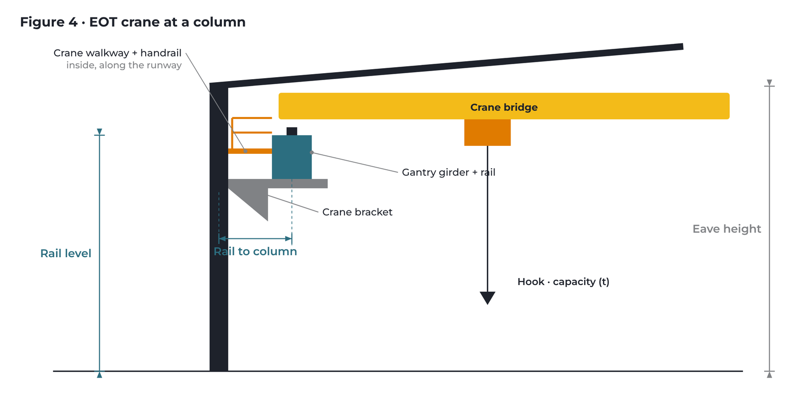
Tick EOT cranes to add electric overhead travelling cranes. The tool puts a crane runway in every module of the frame, adds brackets, girders and rails, and designs the columns for wheel loads, braking and surge. All other crane inputs appear once this is ticked.
| Input | Unit | Default | What it means | Guidance |
|---|---|---|---|---|
| EOT cranes, runway in every module | tick | Off | Adds cranes. In Beam & Column buildings, interior columns get brackets on both sides. | Tick if any crane is planned, even later. |
| Number of cranes | no. | 1 | Total cranes in this building. With two or more, the tool also checks two cranes in adjacent modules loading the same interior column. | Count every crane, in every module. |
| Capacity of each | t | 10 | Safe working load (SWL) of each crane. | 1–100 t. Above 50 t the tool assumes four wheels per end carriage, and real buildings usually use stepped or laced columns. |
| Rail level | m | 6 | Height from floor to the top of the crane rail. Must be below the eave. | Eave height is usually rail level + 1.5–2.5 m for the crane's headroom. |
| Rail to column centreline | m | 0.75 | Horizontal distance from the column centreline to the rail. A larger offset bends the column more. | 0.5–1.0 m |
| Max wheel load (if known) | t | 0 | Maximum static load on one wheel, from the crane supplier's data sheet. | Leave 0 to estimate from capacity, trolley and bridge weight and span. |
| Crane bridge weight (if known) | t | 0 | Self-weight of the crane bridge and end carriages, from the crane supplier. | Leave 0 to estimate. |
| Crane walkways per module | – | None | 1 m wide maintenance walkways with handrails, inside the building along the length of crane travel: none, one side or both sides. About 70 kg per metre. | Many suppliers include one per module. |
| Gantry girders and rails in steel scope | tick | On | Untick if the crane supplier or others supply the gantry girders and rails. Brackets stay in the PEB scope. | Many PEB quotations exclude girders: match the quotation. |
7. Mezzanine floor
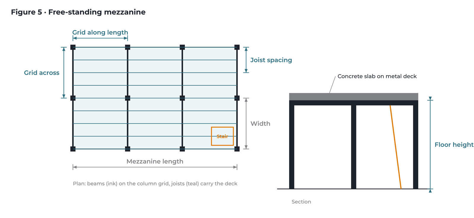
A free-standing steel floor inside the building, on its own columns, with a concrete slab on metal deck. It is not tied to the main frames.
| Input | Unit | Default | What it means | Guidance |
|---|---|---|---|---|
| Free-standing mezzanine | tick | Off | Adds the mezzanine. Other inputs appear once ticked. | – |
| Length | m | 20 | Mezzanine size along the building. | – |
| Width | m | 10 | Mezzanine size across the building. | – |
| Floor height | m | 4 | Finished floor to top of mezzanine slab. | 3–5 m |
| Live load | kN/m² | 5 | Load from people, furniture or stored goods (IS 875 Part 2). | 4 offices, 5 light storage, 7.5+ heavy storage. |
| Concrete on deck | mm | 125 | Total slab thickness on the deck sheet. | 100–150 mm |
| Joist spacing | m | 2 | Spacing of the secondary beams that carry the deck. | 2–3 m for a 125 mm slab. |
| Column grid along length | m | 6 | Mezzanine column spacing along the building. | Larger grid = fewer columns, heavier beams. |
| Column grid across | m | 6 | Mezzanine column spacing across the building. This is the span of the joists. | 5–8 m |
| Staircases | no. | 1 | Steel staircases up to the mezzanine, about 0.25 t per metre of rise each. | At least 2 for larger floors (fire exits). |
8. Canopies
Cantilevered roofs projecting from the wall, typically over loading docks and entrances.
| Input | Unit | Default | What it means | Guidance |
|---|---|---|---|---|
| Cantilever canopies | tick | Off | Adds canopies. Other inputs appear once ticked. | – |
| Location | – | Side walls | Side walls: supported on the main frame columns at bay spacing. End walls: supported on the end-wall columns. | – |
| Number of canopies | no. | 1 | Separate canopies of the length below. | Full-width canopies on both end walls = 2. |
| Length of each | m | 20 | Length of each canopy along the wall. | Usually a whole number of bays. |
| Projection | m | 3 | How far the canopy sticks out from the wall. | 1–8 m; 3–4.5 m over docks. |
| Height above floor | m | 6 | Height of the canopy above floor, for the description sheet. | Little effect on tonnage. |
9. Openings and accessories
Items that add a little steel or appear only in the quantity list.
| Input | Unit | Default | What it means | Guidance |
|---|---|---|---|---|
| Framed openings | no. | 0 | Door and shutter openings. Each adds two jambs and a header in the wall framing. | Count rolling shutters and large doors. |
| Opening width | m | 5 | Clear width of each framed opening. | – |
| Opening height | m | 6 | Clear height of each framed opening. | – |
| Cage ladders | no. | 0 | Access ladders with safety cages to the roof or crane walkways, about 22 kg per metre of height. | – |
| Skylights | no. | 0 | Translucent roof sheets. No change to steel; listed in quantities. | – |
| Skylight length | m | 3.3 | Length of each skylight sheet. | – |
| Louvres | no. | 0 | Fixed wall louvres, listed in quantities. | – |
| Wall lights | no. | 0 | Translucent wall panels, listed in quantities. | – |
| Roof insulation | tick | Off | Adds roof insulation area to the quantities. Its weight goes in Roof sheeting + insulation. | – |
| Wall insulation | tick | Off | Adds wall insulation area to the quantities. | – |
| Anchor bolts in steel scope | tick | On | Untick if the civil contractor supplies foundation bolts. Base plates stay in the steel. | Match the quotation scope. |
10. Design settings
Engineering choices that PEB suppliers make in detailed design. The defaults match common Indian PEB practice; change them only to match a specific quotation or design basis.
| Input | Unit | Default | What it means | Guidance |
|---|---|---|---|---|
| Plate steel for frames | – | E350 / 345 MPa | Yield strength of the plates used to build up frame members. | Most PEB builders use 345 MPa; 250 MPa needs about 20–30% more frame steel. |
| Purlins and girts | – | 345 MPa galvanised | Yield strength of the coil for cold-formed Z purlins and girts. | 345 MPa is standard. |
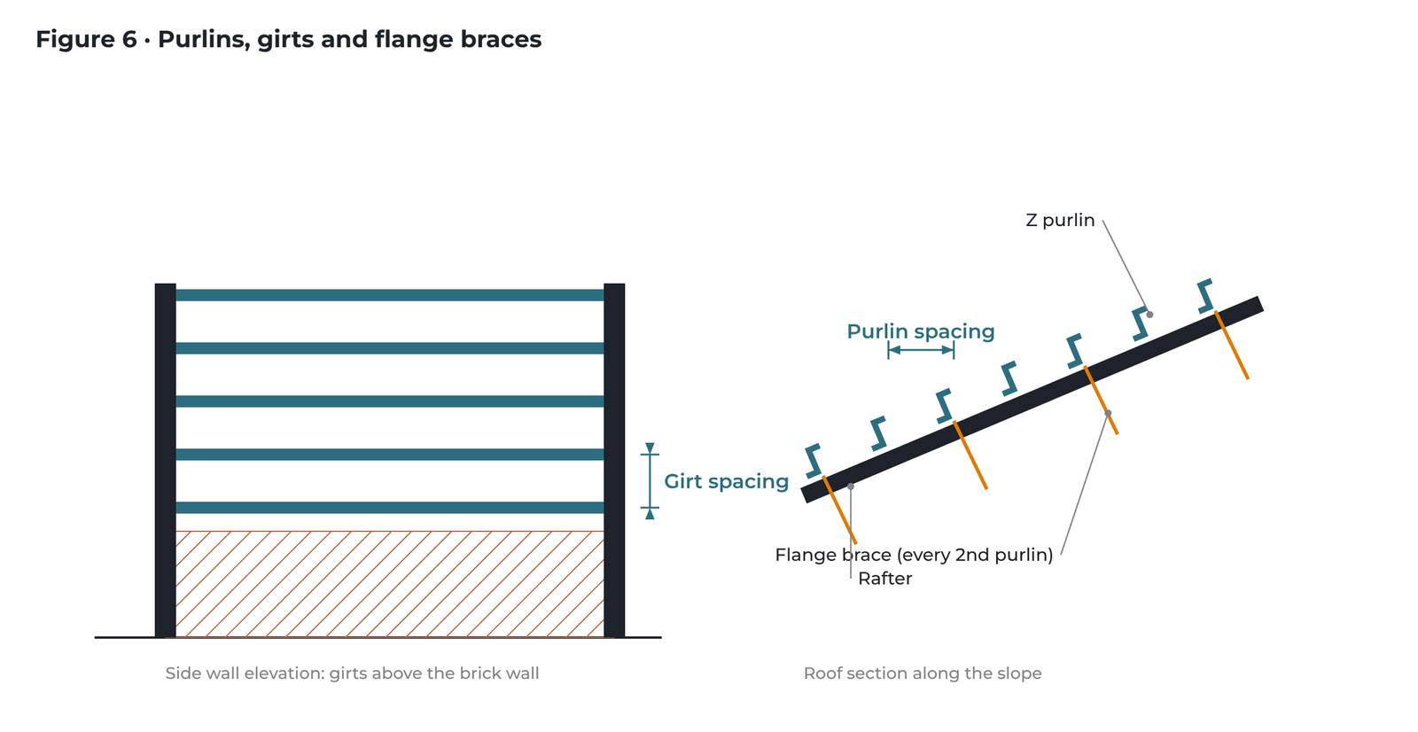
| Purlin spacing | m | 1.5 | Spacing of purlins up the roof slope, set by how far the roof sheet can span. | 1.2–1.8 m |
| Girt spacing | m | 1.8 | Vertical spacing of wall girts. | 1.5–2.0 m |
| Flange brace spacing | m | 3 | Distance between flange braces: small angles from purlins and girts to the inner flange of the frame that stop it buckling sideways. Closer bracing gives lighter frames. | Usually every second purlin. |
| End-wall column spacing | m | 6 | Spacing of the columns across each end wall. Also the span of the end-wall girts. | 5–7 m |
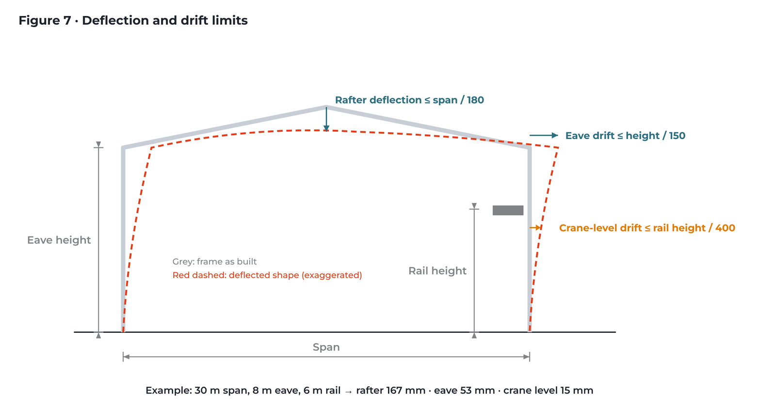
| Rafter deflection, span / | – | 180 | Allowed sag of the rafter under roof live load, as a fraction of the span. | IS 800 Table 6: span/180 for elastic cladding. |
| Eave drift, height / | – | 150 | Allowed sideways movement at the eave under wind, as a fraction of eave height. | IS 800 Table 6: height/150 without cranes. |
| Crane-level drift, height / | – | 400 | Allowed sway at crane rail level under crane surge. Only with cranes. | Height/400 typical, so the crane runs smoothly. |
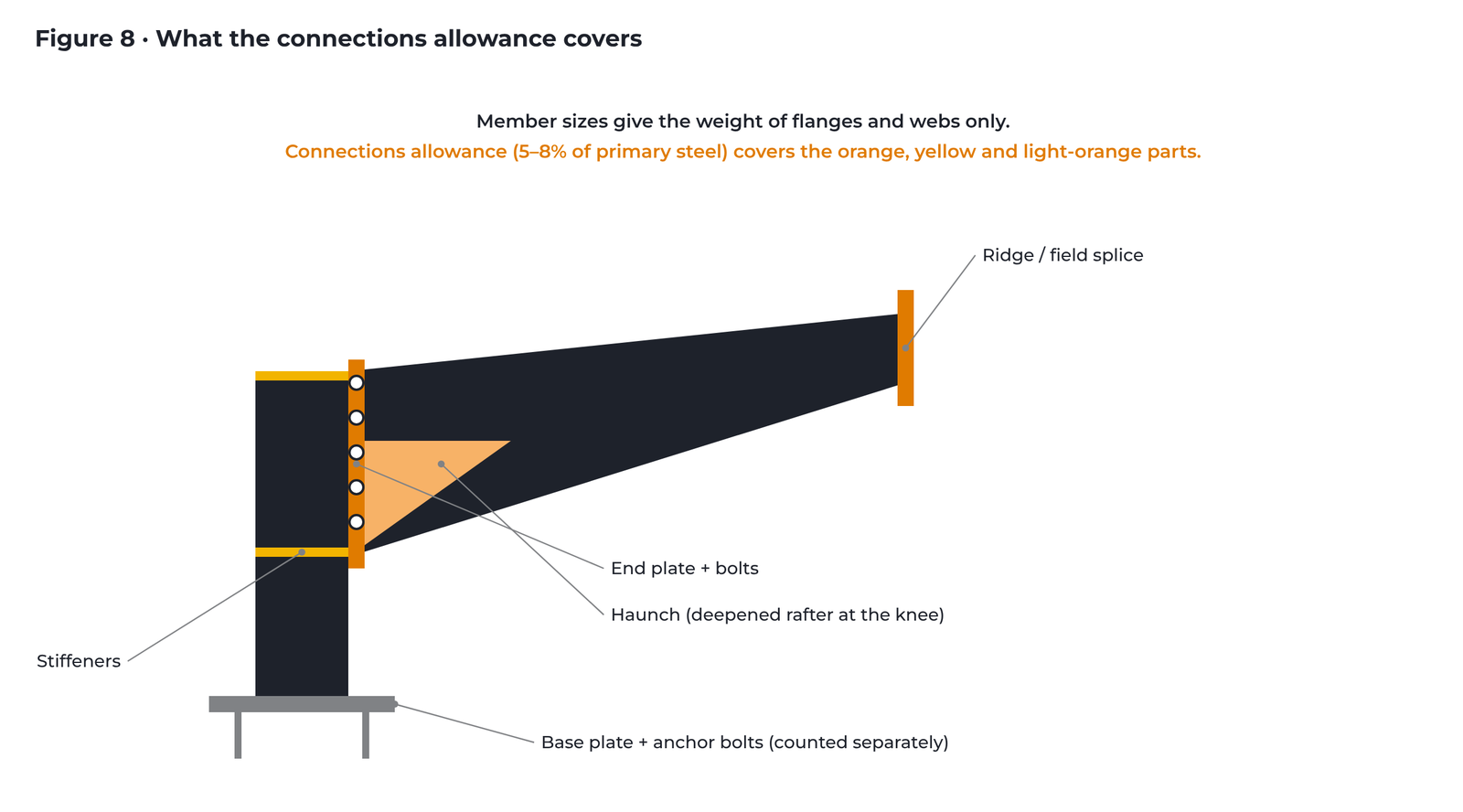
| Connections allowance | % | 6 | Added to primary steel for end plates, haunches, stiffeners, splices and bolts, which the member sizes don't include. | 5–8% |
| Wastage | % | 2 | Cutting and fabrication wastage added to the total. | 1–3% |
How each design setting works
Plate steel for frames. Frames are built up from plates welded into I-sections. Stronger plate (E350, 345 MPa) carries the same load with thinner flanges and webs. Switching to E250 (250 MPa) typically adds 20–30% to frame weight where strength governs; where deflection governs the saving is smaller, because stiffness is the same for both grades.
Purlins and girts grade. The yield strength of the galvanised coil rolled into Z purlins and girts. 345 MPa is the PEB norm; 250 MPa needs heavier sections at the same spacing.
Purlin spacing. The distance between purlins up the roof slope (Figure 6). Closer spacing means more purlins, each lighter; wider spacing means fewer, heavier purlins and a stronger roof sheet. The roof sheet's span table sets the upper limit, usually 1.5–1.8 m for 0.47–0.50 mm profiled sheet.
Girt spacing. The vertical distance between wall girts above the brick wall (Figure 6). The same trade-off as purlins, set by the wall sheet's span.
Flange brace spacing. Frame rafters and columns are deep, thin I-sections. Under uplift or wind, their inner (unrestrained) flange is in compression and wants to buckle sideways. Flange braces are small angles from a purlin or girt to that inner flange (Figure 6). At 3 m, a brace on every second 1.5 m purlin, the frame can use slimmer flanges. Wider spacing makes frames heavier.
End-wall column spacing. Spacing of the columns across each end wall (Figure 3). These columns carry the wind on the end wall and support the end-wall girts. Above about 7.5 m the girts and the end-wall columns get noticeably heavier; 10 m is possible but costs steel.
Rafter deflection, span /. How far the rafter may sag at mid-span under roof live load (Figure 7). At span/180 a 30 m rafter may sag up to 167 mm. A stricter limit (span/240, span/300) makes rafters deeper and heavier. Use a stricter limit under sensitive ceilings, sprinkler mains or gutters.
Eave drift, height /. How far the top of the column may sway sideways under wind (Figure 7). At height/150 an 8 m eave may move 53 mm. Brick walls or glazing tied to the frame may need height/200 to height/300 to avoid cracks.
Crane-level drift, height /. How far the column may sway at rail level under crane surge (Figure 7). At rail height/400 a 6 m rail may move 15 mm. Tight limits keep the crane from skewing on its rails; they often govern the column size in crane buildings.
Connections allowance. The frame member sizes give only flanges and webs. End plates, bolts, haunches, stiffeners and splices are added as a percentage of primary steel (Figure 8). 5–8% is typical; use the higher end for many short members or heavy cranes. Base plates and anchor bolts are counted separately.
Wastage. Plate and coil lost in cutting and fabrication, added to the total. 1–3% is typical; some quotations include it in their tonnage and some do not, so match the quotation when comparing.
11. Reading the results
| Output | What it shows |
|---|---|
| Total steel (t) | Estimated weight for this building, with a likely range. The project total adds every building tab. |
| kg/m² of plan | Steel per square metre of floor area. A quick benchmark: plain clear-span sheds are often 25–45 kg/m²; crane buildings more. |
| Breakdown by group | Main frames, interior columns, end walls, crane steel, purlins and girts, bracing, mezzanine, canopies, connections, base plates and wastage. Tap the i beside a group for what it includes. |
| Governing check | Whether strength, deflection or drift sized the frames, and the governing load case. |
| Frame sketch | Elevation of the main frame with member depths. |
| Description sheet | A text summary of the building, loads and codes that can be copied into an enquiry or comparison sheet. |
12. Frequently asked questions
Why is my figure lower than the supplier's? Check that wind speed, terrain, cyclone factor k4, crane count and scope ticks (girders, anchors) match the quotation. Wind is the most common difference.
Why does Beam & Column save so much steel? Interior columns cut the rafter span, and rafter weight rises roughly with the square of span.
Should I use IS or MBMA? Use Indian Standards for your own budget and for PSU or consultant specifications. Use MBMA to check a supplier's MBMA-based quotation like for like.
Can I trust the city wind speed? It is a starting point from IS 875 Annex A. Always confirm the speed and zone for the exact site and any project design basis.